Synthetic biases
In this tutorial we will see how to use synthetic offsets to calibrate flats and how to determine their level. I will use the terms bias or offset indifferently.
Why (and when) can I use a synthetic offset? #
The main objective of subtracting the masterbias from the flats is to set their zero value so that when dividing the lights corrected by the masterdark, their curvatures are matched, as explained in appendix . This is not about trying to remove readout noise (subtracting a masterframe never removes noise, it removes a signal while adding some noise). And in the particular case of flats, this is neither about removing other level variations, unless your sensor has:
- important ampglow and you are exposing your flats for a significant amount of time (a few seconds or more).
- no thermal regulation under high temperatures, so possibly an important dark current which will make the zero level both temperature- and time-dependent.
The small variations, lines or grid-pattern, that you may have observed over your masterbias in Histogram view do exist, as illustred in the following figure.
In Histogram equalization view mode, a pattern is clearly visible. However, statistics show that these variations are quite small and don’t play a big role comparing to the light recorded in a flat-field frame.
But they are so small compared to the amount and variability in the number of photons received when exposing a flat that they do not really matter. To convince yourself, just remember that you never remove a masterbias from the images you shoot during daylight, simply because there is ample signal and dynamics. This is of course not valid for deep-sky raw images which have very scarce signal.
So instead of subtracting a masterbias which will inherently add some noise, the principle of using a synthetic offset is to simply subtract a level in ADU from your flats before stacking them.
Determine the offset level with an imaging camera #
With an imaging camera, Offset (or brightness or black level) is a parameter that can be defined by the user. The value you set in your imaging software is not the effective level in ADU that can be measured in your bias frames. In order to determine how the setting and the ADU level relate, you can follow this simple procedure. I would recommend you do this even if you never change this setting, to determine the multiplier with more accuracy.
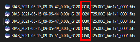
- shoot a series of bias frames, one per setting value. In the example below, with my ZWO 294MC, I’ve used offset settings between 10 to 50 by steps of 10, so 5 frames in total. The possible values are within the range $[0,100]$, but this is specific to each make and model. Never use a setting of 0 as the statistics will be distorted by zero-clipping (this is exactly why camera manufacturers add an offset voltage).
- Open Siril and set
Homewhere your shots are stored. - Convert to a sequence by typing
convert offsetin the command line. - Extract the statistics of the sequence by typing
seqstat offset offset.csv basicin the command line. This will compute the statistics for all the frames in the sequence and save them to file offset.csv. - Open the csv file as a spreadsheet (the values are tab-separated). If you are getting statistics values as floats, not ADU - depends on your bitdepth preference in Siril - they can be converted to ADU by multiplying by 65535 $(=2^{16}-1)$. I chose to plot the median as estimator of location, more robust to outliers (cold/hot pixels) than the mean would be. And I plot it vs. offset setting values which I’ve entered for each frame. If I add a linear trendline, forcing the intercept to be 0, I get this plot:
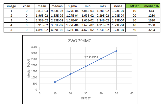
Level in ADU vs offset setting for a ZWO 294MC camera
- We can see that the median level in my biases varies linearly with setting value by a factor of 64, so that
OffsetLevel[ADU]=64*OFFSET. Should I keep the digits? Sure not, we are looking for an integer value. More accurately, we are looking for a multiplier value which is a multiple of 4 for this particular camera, which has a 14-bit ADC. So that I know for sure that there is at least a factor 4 $(2^{16-14})$ involved between the convertor output and the bitdepth of my FITS file (16b). Similarly, a 12b camera should have a multiplier which is a factor of 16 $(2^{16-12})$, while for a 16b camera, there is no way to tell. For instance, for a ZWO 2600MC, the multiplier is 10.
Determine the offset level with a DSLR #
Even though a DSLR is more likely to be affected by sensitivity to dark current, you can still give the same method a try. With a DSLR, there is no such thing as setting an offset value. Still, behind the scenes, the manufacturer defines it automatically with the ISO setting. I have repeated the same procedure with my Canon 700D, shoot a bunch of biases with varying ISO settings, extract the statistics and plot median level vs ISO. I get the curve below:
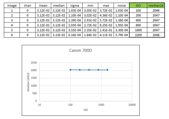
Level in ADU vs offset setting for a Canon 700D DSLR
So it seems that for this model, the offset level is not varying with ISO. The value to use is 2048, which makes sense as DSLR manufacturers very often choose to use a power of 2. It could be that for different models, the ISO-independence is not true or the offset level is not a power of 2, and you should definitely check for your own gear.
And now what? #
Now that you have determined the offset level for your imaging sensor, how to process your flats with this information?
If you process manually:
During calibration of your flats, instead of specifying a masterbias, you can directly type expressions in the folder selector such as:
=2048=64*$OFFSET
The = and $ signs are mandatory for this to work. The level must be given in ADU (not float, even if you are working in 32b).

If you process with commands or scripts:
The command calibrate now accepts passing an expression for the -bias= option:
calibrate flat -bias="=256"calibrate flat -bias="=10*$OFFSET"
The =, $ as well as the quotes around the expression are mandatory for this to work. The second expression needs as well that your imaging software writes a key OFFSET or BLKLEVEL in the FITS headers to log the offset setting. The level must be given in ADU (not float, even if you are working in 32b).
Appendix: Understanding how the flats correct the lights #
The point of this section is to give a bit more insight in how the different levels play a role in the correction of the lights by the flats. We will disregard here any considerations about noise (again, noise does not vanish with masters subtraction or division, it decreases by averaging over many realizations of the same random process). We also disregard particular spatial patterns such as ampglow or dust.
If we try to quantify the intensity of background pixels in the different frames we have, we can write the following expressions:
For the lights $L$, the first part is a spatial illumination component, i.e., $a - b(x-\frac{W}{2})^2$. We have chosen here a quadratic variation with a maximum value $a$ in the middle of the frame of width $W$, even about the center of the sensor. This is not the exact spatial shape of vignetting but it is a good enough approximation to understand how it works. In addition to this spatial illumination term, there is a term varying with exposure time which is usually named dark current ($d_{rate} \times t_{lights}$) but which does not depend on the position of the pixel on the sensor. And finally there is a pedestal, i.e. the offset. This offset is present in any frame which is shot, so that we find it in all the expressions.
The darks $D$ not beeing illuminated, they only bear the dark current term, with same intensity as lights as they are shot for the same amount of time, and the offset term.
The flats $F$ also have a spatial term, proportional to the term found in the lights. The factor $K$, larger than 1, simply shows that their intensity is larger. To write this, we only need to assume that the pixels respond linearly to the number of photons they gather, which is sensible. We could also have written a dark current term, proportional to the exposure time of flats. But unless this time is significant, we can assume it is negligible. If it is not the case, then it means you need to shoot dark flats, or at least to assess their level.
And finally the offsets $O$ only measure the offset level.
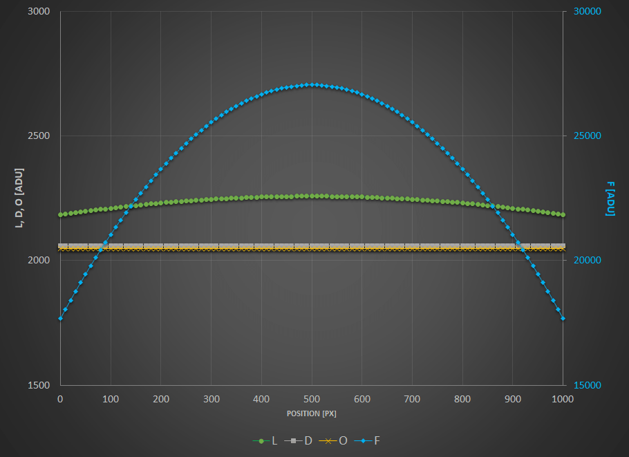
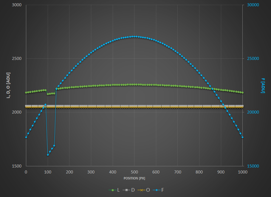
To visualize these levels, I have plotted here-below these expressions as curves wrt. position on a frame and I encourage you to do the same and to play around with the inputs.
- $a = 200 \text{[ADU]}$
- $b = 0.0003 \text{[ADU/px}^2\text{]}$
- $d_\text{rate} = 1 \text{[ADU/s]}$
- $t_{\text{lights}} = 10 \text{[s]}$
- $o = 2048 \text{[ADU]}$
- $W = 1000 \text{[px]}$
$L$, $D$ and $O$ values in ADU are given on the left scale while $F$ are on the scale reported to the right.
Now what does calibrating your lights mean? When you calibrate your lights, you perform the following operation: $L_c = \dfrac{L -D}{F-O}$.
The term $F-O$ is a flat from which you have subtracted the offset level (whether it is a masterbias or simply a level, i.e. the whole point of this tutorial). This is the operation performed prior to stacking your masterflat. And the term $L-D$ represents a light from which you have subtracted the dark current level and the offset, i.e. a masterdark. If you replace with the expressions shown above, you end up with the following: $L_c = \dfrac{1}{K}$.
No spatial variation term is left, you have flat-fielded your lights! Getting a sensible value in ADU (and not $1/K$) is what Siril does when you check Auto evaluate normalisation value in the Calibration tab.
And you can try with any other combination, no other will get rid of spatial variations.
Just to illustrate this, I have plotted below the result of different combinations. To put everything on the same scale, all the results are normalized to have the same intensity of 1 in the middle of the frame. The following tests are shown:
- $L-D$ : you have just shot darks.
- $L/F$ : you have just shot flats.
- $L/(F-O)$ : you have shot flats and corrected them by an offset (either a master or a synthetic one).
- $(L-O)/(F-O)$ : you have just flats corrected by offset. But you have subtracted the offset from your lights as well.
- $(L-D)/F$ : you have shot flats and darks but no offsets.
- $(L-D)/(F-O)$ : you have done everything by the book.
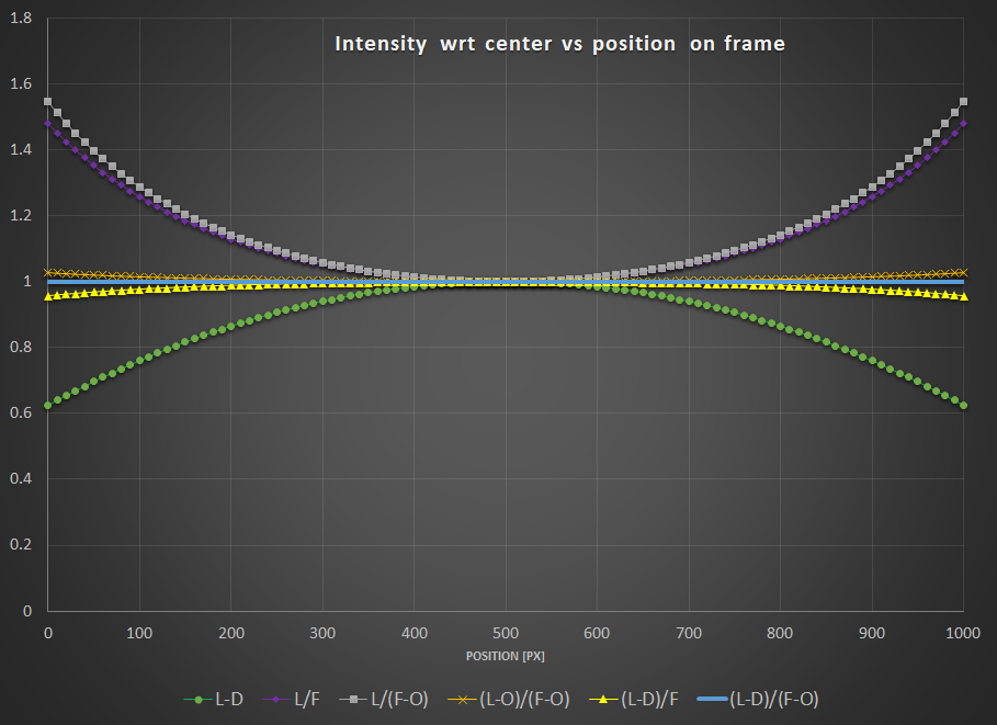
Interestingly, you can notice that:
- $L-D$ shows obviously no correction for vignetting.
- Both $L/F$ and $L/(F-O)$ show overcorrection or inverse vignetting.
- Getting very close to the optimal result, $(L-D)/F$ and $(L-O)/(F-O)$ shows a field almost flat. This, of course, will depend how much your sensor has dark current and how much vignetting your optical train shows.
- The reference calibration gives a flat field.
The conclusions that you can draw from the above are:
- You are better off correcting your lights with offset (masterbias or simply a level) if you have not shot darks.
- Even better, if you don’t have time to shoot a series of darks, it is probably worth shooting at least one dark, measure its median, and subtract this (synthetic) dark from your lights. It will of course not correct for ampglow or enable hot pixel correction, but your lights will at least be flat!
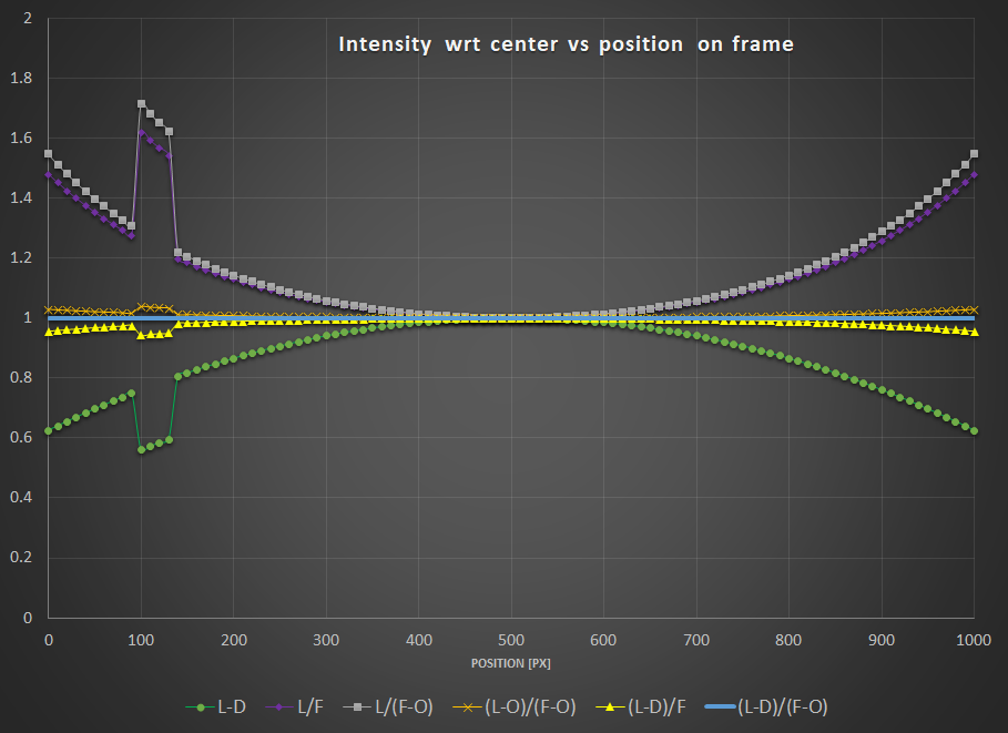
Now what about dust…? In order for your flats to also correct for these nasty spots, the sad news is you also need to get all the calibration frames in the equation. I have added a small local ADU deficit in the lights and flats to illustrate this effect.
As you can see, only the combination $(L-D)/(F-O)$ can get rid of it.
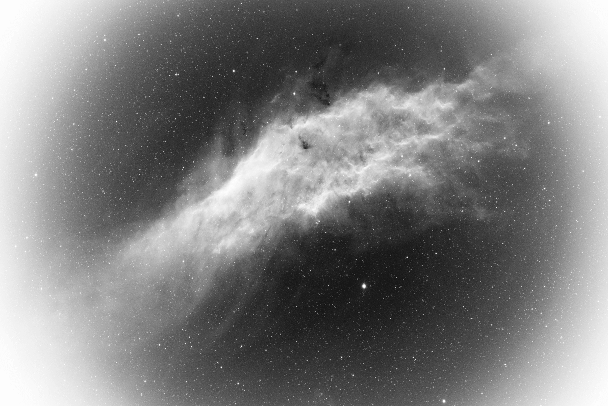
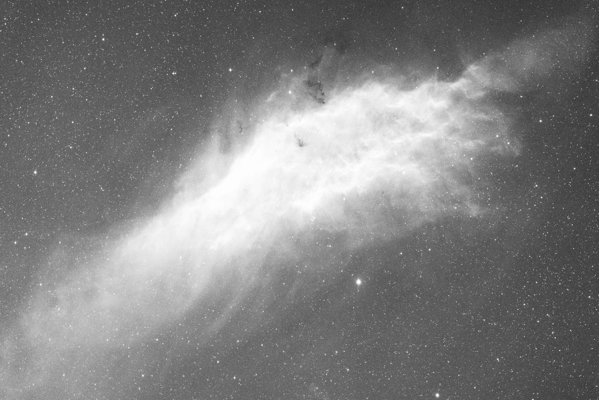
To further illustrate the equations and curves above, nothing is better than a real-life example. All pictures below are shown courtesy of G. Attard.
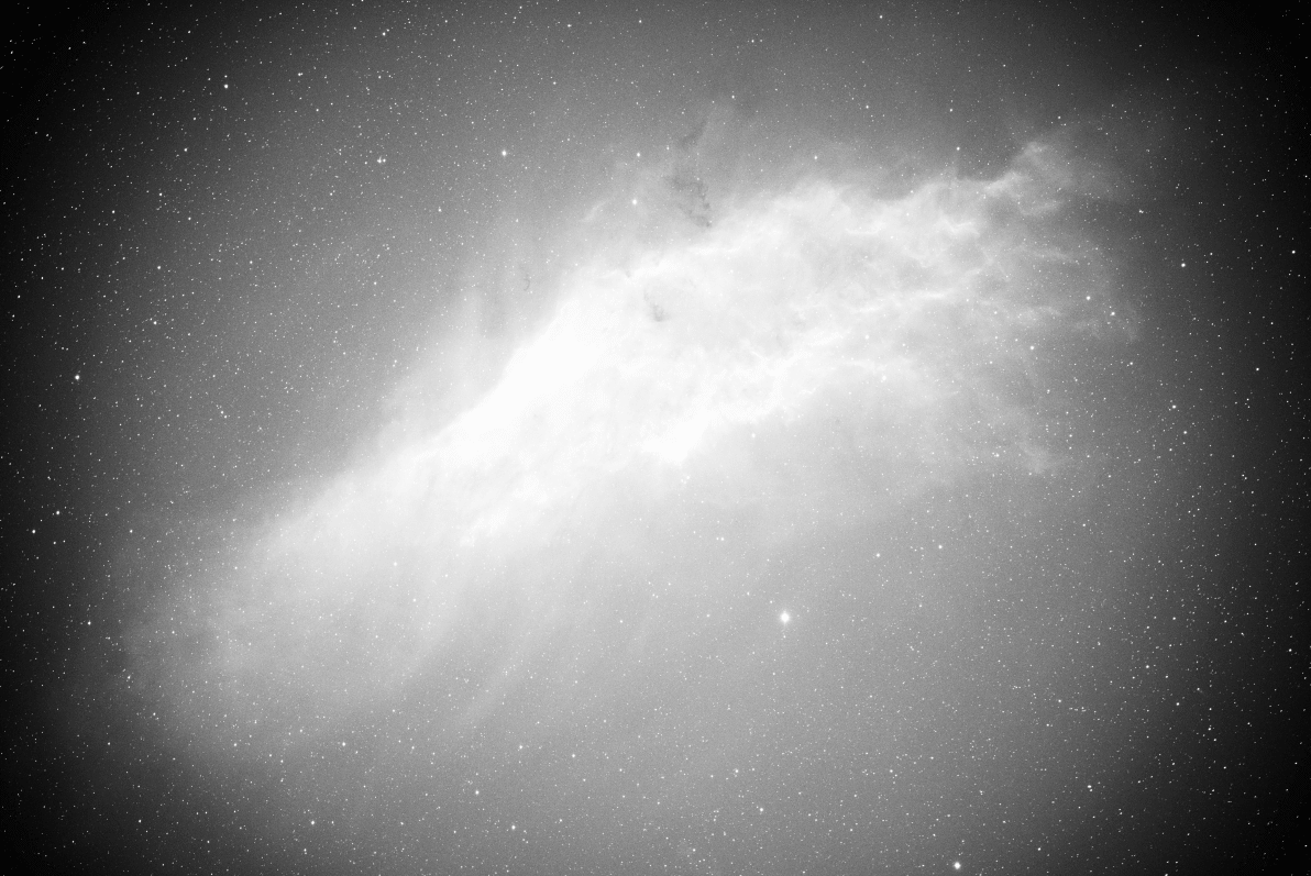
$L-D$
$L/F$

$L/(F-O)$
$(L-O)/(F-O)$

$(L-D)/(F-O)$